Monday, May 30, 2011

WS3A Gneral Lab Scope

Make Toyuta 1ZZ engine:
Signal Name : TPS (Linner)
Volt/division/range : 1 Volt
Time/division/range: 1 second


Wveform of TPS sensor Aroow A represent the throttle is wide open wich i set the osclecope voltage 1 volt per division wide open of thrttle is nearlly 4 volts . Arrow B represent the throttle is closed , also the C is same B in 2 seceds wich the time per division i had set 1 second per division. When the throttle open the voltge signal goes up , normally close to open voltage 0.5v - 5v in this sensor.

Explain in detail an electrical fault that would make this unit operate incorrectly.The signal voltage drops to zero because the wiper arm on the signal wire fails to make proper contact with the carbon resistor this is called "drop out".

Explain why this condition would cause this unit to malfunction.Because the ECU uses the variable signal voltage to determine the throttle position 0.5v being closed and 4.5v being wide open throttle. If the signal voltage goes to zero volts because the wiper loses contact with the carbon strip the ECU will think the throttle is closed.

The condiition of TPS sensor in this engine is ok , cause the out put signal is changing in diffrent angle of throttle , wich shows on oscclicope patrren , we can see in close throttle and open throttle diffrent pattren wich from close to open the pattren goes up . I can say that sensor workin perfect.


WS3A
Signal Name; MAP Analoque
Volt/division: 0.5v
Time division: 2 seconds


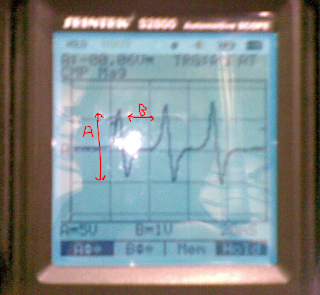
The output from the sensor with show rise and fall votage dipinding upen the vacuim sens. When the engine is sataitonary or the throttle is wide open zero vacuim will be reduced and voltage reach in this graph nearlly 3 volts will be seen a vacuim is applayed the voltage will reduced. the example waveform clearly demonstrated at idle voltage arorund 1v all the throttle open the vacuim in mainfold drop and higher voltage for these condition Arrow A open throttle Arrow B closed throttle .

Explain in detail an electrical fault that would make this unit operate incorrectly.A bad earth due some grease or dirt, gives a resistance in the earth wire. This would give a lower out put signal voltage this would effect the air/fuel mix, spark advance and injector pulse with.

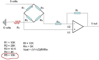
Explain why this condition would cause this unit to malfunction/ Use mathematical equations to back up your explanations.Because there is an extra resistance in the earth wire more voltage will be use up in the MAP sensor circuit. This will cause a lower out put signal voltage. This is a simplified example of a MAP wiring diagram with a resistance in the earth wire.

Without the resistance in the earth wire Vout = 4.5v. The calculations with resistance in the earth wire.

Vd = Vin(R1/R1+R2)

5(10k/10k+28k+10k) = 10000/48000 = 0.2
5x0.2 = 1.04
5-1.04 = 3.9
V1 = 3.9

Vd = 5(10k/10k+4k+10k) = 10000/24000
=0.416
5x0.416 = 2.08
5-2.08 = 2.92
V2 = 2.92

Vout = (V1-V2) Rf/Rin

= (3.9 - 2.92) 1000/5000
0.98x2=1.96
Vout = 1.96
Diffrent  betwen good and bad earth 2.5 volts

In this graph is  bad earth you can see point  voltage is lower than the first graph .

Explain how this condition would affect the operation of the vehicle?

 The MAP sensor measures the air intake volume it has a major part in determining how much fuel to inject and also the ignition timing so a low voltage signal would make the engine idle rough or make the engine to stall, or should be engine runing rich or lean.


WS3 General Lab Scope
Make and Modle: Toyota 1ZZ engine
Signal Name: Injector
Volt/division/range: 20 V
Time/division/range: 5 ms


Arrow A shows the supply voltage to the injector in this case 14.4v. Arrow C when the injector is switched on, because the injectors are earth triggered the voltage drops to 0v for approx 2ms this is wile idling. Point B is the voltage spike induced when the earth is switched off approx 60v.
At point D back to EMF.
Fuel injector. supply engine with fuel  It remains closed and opens only when fuel needs to be injected, fuel keeps under pressure in the fuel line.


Ws3
Make & Modle: Toyota 1ZZ engine
Signal Name: Oxygen Sensor
Volt/division/range: 0.5V
Time/ division/range: 1s


oxygen sensor. The sensor is part of the emissions control system and feeds data to the­ engine manegmenment computer. The goal of the sensor is to help the engine run as efficiently as possible and also to produce as few emissions as possible.

Explain the operation of the sensor or device using the graph:
The above graph shows that the engine is running in close loop. It means that engine is warmed up. The point B in graph where it touched the highest voltage shows that the engine is condition is rich and lowest C point shows that it is lean.

WS3 A General Lab Scope
Make & Modle : toyta
Signal Name: RPM (Mag Crank) Analuque
Volt/division/range: 5V
Time/divison/range: 1 ms

When the Magnetic Pulse Generator type  is excited by the toothed disc it's in close proximity with, it starts to produce an Analog Voltage Signal. This Analog Signal is created without the help of an external power source! As long as the engine is turning, either because it's cranking or running, the Signal is being produced. When the engine is off, so is the Sensor.
So the analogsignal As it applies to Crank and Cam Position Sensors, it's a signal that oscillates between lows and highs the whole time it's being produced WITHOUT ANY ABRUPT FALLING OR RISING EDGES. When the signal goes low, it never completely turns off. And when it goes high, it must come down again. This process is repeated over and over as long as the toothed disc is exciting it.
Looking at the oscilloscope waveforms  at point A high signal and point B falling the signnal.


WS3A General Scope
Make& Modle Toyota 1zz
Signal Name: ECT
Volt/division/range; 1V
Time/division/range: 1S

The ECT sensor cahnge their resistance depending on temperature , as the temperature increasing the resistance of NTC will decreases abuot 240 K ohms at 10 degree to about 200 ohms at 80 deggre. The ECU looks at cslculate signal ECU usually 5 volts supplay is used, that way ECU can calculate the temperature at sensor two resistor in sensor must drop accross the resistance.
I had get this waveform in cold engine that can take time to drop the voltage , on picture the waveform is not change because the engine was cold.

Explaine in detail an electrical faults that would make unit operate incorrectly:

A fault leading to excessive resistance or a lack of resistance in the circuit.] Extreme corrosion at the ECT connector will lead to excessive resistance in the circuit. This condition will raise the ECT signal voltage leading the ECU into calculating that the engine is cooler than it is. A cold engine will make the ECU increase injector pulse-width, therefore, creating excessive CO at the tail pipe. In extreme high resistance conditions, engine flooding can occur, since the ECU reacts as if the engine temperature is at subzero temperatures. If on the other hand, a lack (shorted) of resistance is present at the ECT circuit, the opposite of the previous will hold true. Lower than normal ECT circuit resistance will lower the voltage signal across the sensor tricking the ECU to act if the temperature is higher than what it really is, which in turn makes the ECU reduce injector open time or pulse-width. Such a condition can cause a lean misfire or even a no start on a cold engine, due to the fuel starvation effect caused by the ECU’s reduction of injector pulse width.

Explain why this condition would cause this unit to malfunction / use mathematical equations to back up yor explanation.
First have lock the ECT sensor diagram wich has three resistors one in ECU and two resistors in seriuse inside ECTsensor and 5v refrence from the ECU to sensor.
This one is good working sensor use the calculation :
For example : 
Vs=5V
R1= 2000 ohms 
R2= 1000 ohms
R3 = 2000 ohms
Calculation:  Vout = Vin (R1/R1+R2)
Vout = 5V * 2000ohms/2000ohms+1000ohms= 3.33V
Vout = 3.33V
If in this circuit is connector corrosion there will be resistance in circuit fist look in the diagrm and then we can see the diffrince of output voltge after calculation.


R3=1500ohms 

Vout = Vin (R1/R1+R2+R3)
Vout = 5V * 2000 ohms/2000ohsms+1000ohms+1500ohms= 2.22V
Vout = 2.22V
diff : 1.11V

WS3 Grneral Lab Scope
Make & Model: Toyota
Signal Name: RPM (CAM) Analge
Volt/divsion/range: 5V
Time/divsion/range: 20ms
Arrow  A peak to peak voltage and Arrow B time in ms.
CMP Sensor is Magnetic Pulse Generator, it will tested with a Multimeter in AC Volts mode. Why? Well, because the Signal that these sensors generate is an Analog Voltage Signal and this Signal can only be measured in AC Volts mode on your Multimeter (or Oscilloscope).
When the Magnetic Pulse Generator type is excited by the toothed disc it's in close proximity with, it starts to produce an Analog Voltage Signal. This Analog Signal is created without the help of an external power source! As long as the engine is turning, either because it's cranking or running, the Signal is being produced. When the engine is off, so is the Sensor we can see on oscilloscope waveform the signal goes high and low , when the signal goes low it;s not complitly turns off and goes high it must go down.

WS3 General Lab Scope
Make & Model: Tyota 4A- FE engine
Volt/division/range: A , 10V & B, 10V
Time/ division/range: 2ms
This is 3 electrical connection with a voltage supplay of battery ether double switched earth path, the rate at switch the earth path is switched is determined by the electronic control moudle (ECU)to maintained by prerequisted speed according to it is programing the double switch earth system will switched the valve in both diricction.

WS2 Flash Codes

Flash Codes

We used for this expeirment Toyota 4A - FE engine

Using the workshop manual follow the procedure to extract the codes, explain briefly what is the procedure:
 

 We found the diagnostic plug on the engine and by using the workshop manual and with tutor advise, we turned the ignition on, without turning the engine on. With help of connector, having cinbuilt fuse, we connected TE1 and E1 of TDCL. Then we checked the warning light on the instrumental panel. It was indicating two fault codes after one another with a little time interval between them. The lowest code appeared first which was 22 for water temperature. The next one was 31 for MAP sensor and then 41 for TPS and 24 for IAT Sensor (according to workshop manual). After completing the check, we disconneted TE1 and E1and turned the ignition off
Code number
System affected
Condition described
     31
MAP Sensor
disconnected
     22
Water Temperature
disconnected
     41
TPS (Throttle Position sensor)
disconnected
     24
IAT (Intake Air Temperature sensor)
disconnected
 
Visual inspection to find fault:
Describe the problems you found;
We took the three sensor out of there connections and according to the manual instructions we connected the two connections in the diagnostic plug and then switched on the ignition. we found that the flash on dash board blinking in out of order. Then we calculated the number of blinks on dash board and saw there is a pause between two continuous blinks and after counting the number of blinks in order wise, we matched those with the manual faults code and found the problems.
 
 
Repair fault:
Plug back in the connector, or repair problem found
Describe what you did:

After turning the ignition off,  putting the every sensors back in their places and leveing the coniction in diagnostic plug as it is we switched on the ignition again . We found there are same codes coming up again even after repairing the problems.
 
Clear Codes:
Discribe what you did to clear the codes
 
I took the connection wire out from the dignostic plug . Then i disconnectecd the battery and reconnected it again to clear the codes.
Recheck the codes and record codes in the system.
After reconnecting the battery and switching the ignition on, we found that the flash light on dash board is working normal.

7. How could the faults found affect the engine performances?

The ECU will receive wrong signals from sensors and process wrongly which could effect engine performance.

8.  Discuss what other tests you should be doing once you have found the fault codes:

we will do the oscillation test on the sensor whether it is working propeerly by bac probing.

Sunday, May 29, 2011

WS1 petrol Fuel Injector Testing

WS1 Petrol Fuel Injector Testing


1. Listening the injectors sound used the stethoscope at idle engine, i had test all of injectors .
Comments; All the four injectors have the same sound.


Checking voltage to the injectors when idling and key on. battery voltage 14.06 volts.

Recording voltage at each injectors .


6 Set the multimeter to read  Hz , and with engine idling, record the reading for each cylider in the box below.

Cyl #2
Cyl #1
Cyl #3
Cyl #4

13.53
12.45
12.44
12.50
HZ


In this picture showing Cyl #2 reading in Hz ( at Idle 12.45 Hz).

7. Next multimeter still set to read Hz but in increase the engine RPM , recoording in box below.
Cyl #2
Cyl #1
Cyl #3
Cyl #4

32.15
32.91
32.12
32.25
HZ
In this reading multimeter Cyl # 1 wich is 32.15 Hz.

Cyl # 4 record 32.25 HZ

Furmula :
"Puls width ms = (% Duty cycle / 100) / Frequency"
Show your calculation: 98.1%/100/ 13.53Hz = 0.07250ms.

Calculate Time @ Idle:
Cyl #1: 98.1% / 100 /13.53 Hz= 0.0725 ms
Cyl # 2 ; 97.6% / 100/ 12.45 Hz= 0.0783 ms
Cyl # 3:  97.6% / 100/ 12.44 Hz= 0.07784 ms
Cyl # 4;  97.5% / 100/ 12.50 Hz= 0.078 ms

Calculate Time when revved:
Cyl # 1: 82.2% /100 /32.15 Hz= 0.0277 ms
Cyl # 2: 82.3% /100 /32.91 Hz= 0.0250 ms
Cyl # 3: 88.85 /100 / 32.12 Hz = 0.0276 ms
Cyl # 4: 82.2%/100 / 32.25 Hz= 0.0254 ms

I had check supply voltage to injectors and i showed that they all got approximately 14.6 volts.

Then we started the engine and back probe to injectors ground wire and connected our  LED tester to battery ground terminal (negative). When we touch ground wire of injector with engine running the LED light were flashing really fast even on idle and after increasing engine RPM's it went even faster, so that showed that all injector are triggered with ground wire and they all working properly and that with more engine RPMs frequency increases so they mast open faster. The reading is acceptable for me.

Tuesday, May 24, 2011

Input Sensors and Actuators On Vehicle

Toyota 4A - FE engine
Voltage to the fuel injector: 14.49V
Supplay voltage is very important for injectors to have power to operate the injectors.

1.5 : If the voltage supplay is low at injectors it may effect open time and duration of injectors, and it will effect performance of the vehicle.

1.6 full circuit diagram of fuel injectors including power supplay , realy ,and ignition switch.
2.1: Refrence Voltage at TPS Sensor:

There are two types of TPS sensors, one is a switch and another potentiometer or linear resistor type. Linear resistor has got 5 volts reference voltage (supply voltage) and a variable resistor track inside and varies output voltage depending on variable resistor. When throttle closed resistance is high and output voltage low, but when its fully open resistance is low and output voltage is high. With this sensor ECU always know at what state is a throttle and can determine how much fuel to add and use emission systems and actuators when vehicle at light cruise. When reference voltage incorrect because high resistance in supply wires (corroded or not plugged in properly) or broken wire dameged inccorect testing this can cause ECU thing wrong and receved half open throttle signal when its wide open. This can effect on fuel economy, emissions and incorrect engine performance. Also ground wires can cause problems, good ground voltage drop reading is usually lower then 0.05 volts if they have a high resistance at ground because of loose connection or corroded wires the can create a high voltage drop at location of the problem and also effect output voltage to ECU from TPS esnsor. And finally ECU ground should be in good working order as it can effect our reference voltage to the sensors, not just TPS as most of the automotive sensors use 5 volts as a reference voltage. So its important when testing TPS to check first supply voltage or reference voltage and second good ground to the sensor. Also some TPS sensors have a fourth wire which can be an idle switch, this is when throttle closed and no air coming to the engine, so ECU know that it need to open idle control valve to keep engine running.
Other type is a switch, its only shows engine 3 modes, idle, light cruise and wide open throttle. Simple but still sensor. Not used on late model cars as less accurate.


2.3 ignition on
2.4 reading of meter; 4.95 Volts

Grond at TPS sensor:     3.3 Record of voltage engine start reading 0.2 volts

Throttle POsition Sensor return / otput:
4.2 record of reading in on ignition 0.55V


4.3: Halp throttle open meter recording is 2.005 Volts

4.4: Full open thrttle engine not runing only ignition on reading obout 3.8 volts.

4.5 Slowly open the throtttle from the closed position to the full open position , the meter resding is slowly increase we can in the next vidio


4.5 The four wires going to the TPS continue with these , the metre reading 0V when throtlle is closed, and 12- 14V when the throttle is opened


      closed throttle reading is about 3.3 mV

          fully open throttle meter reading is 13.31 volts.

4.91 Circiut diagrm of TPS
My all explainiton and answers of qutions No; 2.5 , 2.6, 3.3, and 3.4 are up under 2.1 refrence voltage.


5.2 Record wire colousrs and voltagebelow:
Idle wire : colur Black
Volts at idle ; 0.08V
Volts apart throttle or open throttle: 10.70 volts
Wide open thrttle wire colllur: Black
Volts at idle or part throttle: 10.24 volts
Volts at open throttle : 0.00V
Note: we tested the throttle position switch on Nissan OHC engine wich has all of three wires in black colours.
here picctures of TPS switch below.

          TPS swich output voltage @ Idle 0.08V
                   TPS switch volts at Idle or part throttle 10.24 volts

5.3 Circuit diagram of TPS switch.
This positon sensor is contact switch an ECU refrrence voltage to ground , this switching action cause the signal at the ECU to go low whenever the swith contact are closed. Reffirng to voltage IDL signal voltage is low when the throttle is closed and goes high when the throttle exceced about roougly 25 degree open. PSW voltage is high untel the throttle opens about 70 inch then goes low again.

ECT (Engine Coolant Temperature) Sensor
6.2 Engine ignition is On but not start
6.3 meter reading 3.59 volts , good connection
6.4 enine is normal operation temperature it was cold , and this was the right temperature of engine


6.6 In this pictuure reading of meter the engine is start and wrmed reading is 2.67 volts.
6.7; Awarmer engine usailly show lower voltage Yes we can see in cold engine i have got reading 3.59 volts and warmer engine 2.67 volts.

6.8 Discribe how an ECT sensor works

Engine coolant temperature sensor (ECTS) is located in the coolant passage of the cylinder head for detecting the engine coolant temperature. The ECTS uses thermistor whose resistance change with the temperature.The electrical resistance of the ECTS decreases as the temperature increases, and increases as the temperature decreases. The reference 5V of the ECM is supplied to the ECTS via resistor in the ECM. That is, the resistor in the ECM and the thermistor in the ECTS connected in series. When the resistance value in the thermistor in the ECTS change according to the engine coolant temperature, the output voltage also changes.

6.6 How the ECT sensor voltage affect the fuel injection output from the ECU'
The fuiel injector duration and control the ignatin also control the ignition timing using the information of engine coolant temperatureto avide the engine stalling and improvedriviblity.
6.10: If ECT sensor creat wrong it it should be send incorrect voltage to ECU . That cause engine runing wrong The ECU does not know how is the temperature of engine the big diffrency is fuel/air ratio should engine runing rich or lean . My experince it cold the engine hard to start after starting engine is missfirng.

7.0 Ground coolant temperature sensor

7.4 Strat engine recording voltage on meter is 35.6 mv ( good grond will usually read less than 0.05 v and some manufacture is say 0.10V ) in this experment i had good ground.
7.5 what does this voltage tell you about the ECu earth .
The ECU ground is importannt , ahigher than spacifaicaton reading will also be caused by poor gruond at ECU wich the ECT is depent on for proper operation.
7.4 what could go wrong so that the ECU earth is not good.
We can see in the diagram the ECT sensor ground connectet to ECU if the ground is not good the circuit is not complate there is only one refrence volatge nogrond the ECT sensor not working.
   Circuit ddiagram of ECT sensor and inside detail of ECU .

4.0 RPM Snsor Or Crank Positon Sensor (CKP):

4.5 I had set the multimeter on AC volts and try diffrent wire then i get the correct wich the AC readinge meter 4.75 AC volts.
4.6 Then i had increase engine RPM abuot 2500 rpm recording from the meter is 7.96 volts (wich is AC volt).
4.7 Then return the to Idle speed and switch the multimeter to DC volts . in this picture you can see 0.90 volts at idle

4.8 Then i had increase engine RPM to about 2500 rmp, i get 1.495 volts .


9.4 I witched the vo;tmeter to read Hz . I record the reading from the meter 653.6 Hz.

4.10 In this picture we can see incresed engine RPM to about 2500 rpm the meter reading is 2.088 KH and then returne the engine to idle.
Here is some readings of RPM sensor in AC volts, DC volts and Hertz.
We used magnetic pick up sensor and AC volts and Hertz showing better then DC volts that its working.
This type if RPM sensor is an AC generator, it produce AC voltage when rotating and the number tips on the shaft indicate on number cylinders in the engine. AC volt function of multimeter tells us how much voltage it generate for every tip passing the sensor magnetic pick up and a Hertz tells us how fast its rotating, as if speed of the shaft increased it
increases frequency of rotation, so it start to rotate faster and get more revolutions per minute. Most of this sensor has got adjustable gap between tip and magnet, so if the gap is too big it wont generate signal or it could be weak and not enough to work properly, also they have a certain life and if not working, must be replace as non fixable item., if theECU did not recive the correct signal from the RPM or crnk sensor it cause faulty sensor, shorte or grond wire, or loose connection or faulty signal converter.
4.15 circuit diagram of RPM and Crank postion sensor below.

 MAP or MAF Sensoor:
5.6 I had turn on the engine and folow the instruction for getint in idle accliration .
5.6 in this picture the reading the igntion is ON but engine not start multimeter reading is 1.83 Volts.
9.0 IAT (Intake Air Temperature), ACT (Air Charge Temperature), or MAT (Mainifold Air Temperature) Sensor.

9.3 I had set up the meter to read the DC volts and attach the red lead to pin and the black probo to the ground .
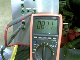
9.4 Recording the reading from multimeter 3.182 V , that is the good reading ,
9.5 Is the reading more or less than the readiinng you had ECT?
Less than ECT.
Does this show the IAT sensor is colder or hotter than th ECT sensor?
Hotter than ECT.
9.6 Discribe how the IAT sensor works.

The IAT sensor resistance changes in ressponse to the intake air temperature , the sensor resistance decrease as the surronding air temperature increases , this provides a signal to ECU, indicating the temperature of the incomig air change.

IAT is used to correct fuel quantity (puls width) since air temperature effects air desinty.

Properly functinig inttake Air Temperature (IAT) sensor shold exhibit the risistance valves indicate in this chart
9.9 Describe what could go wrong to create an incorrect IAT signal for the ECU.
Faulty IAT sensor, loose connection, bad ground, high risstance in the circuit or open the circiut.


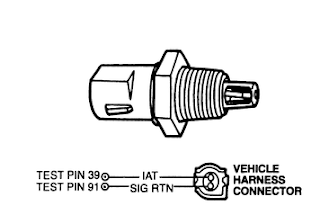
9.10 Wiring diagram of IAT senor including incide ECU detail


5.7 The engine is start in Idle the reading of multimeter is 0.60 volts
5.8 After short acceleration of engine got the reading is 1.052 volts.

Desribtion:

Inside MAP sensor is a silicon chip which changes resistance with different pressure inside intake system and this changes output voltage to ECU. When engine at idle its almost no pressure inside intake (vacuum) so its gives low voltage output, but when throttle open, engine starts to accelerate and pistons suck more air inside, they create certain pressure under different engine loads and change output signal of MAP. This sensor tell ECU how much load on the engine and how much goes in so it can choose how much fuel to inject. Also inside map sensor is a Winston bridge with one constant resistor and one variable resistor (silicon chip). It could be a lot of things which can interrupt this sensor, such as vacuum leak from manifold (hole in gasket or rubber hose), also if silicon chip damaged it also will effect output voltage, wire connections of ground or reference voltage can be corroded or loose.

5.13 Circuit diagram of the MAP sensor .


10.2 In this expermint i had setting multimeter in diffrent setting (DC, AC volt, Hz, %Duty Cycle).
10.3 Recording meter of diffrent setting are below.
DC Volts 125.3 mv
AC Volts 1.270 Volts
Hz (hertz) 25.27 Hz
10.0 Camshft Position Sensor (CMP)
% Duty Cycle 82.7%

                                           DC volts: 125.3 mvolts
                                          Hz : (hertz) 25.27 HZ

                                            % Duty Cycle: 82.7%
The CMP sensor provide the campshaft position information, called the CMP signal , wich is used by the power from (PCM) for fuel synchruoizte.

AC voltage will move between 0.3  - 1 AC voltage . The AC voltage whole time engine is cranking this is normal , if the sensor is bad the multimeter will not disssplay any  AC voltage.
AC voltage increases with engine RPM, so the faster the engine cranks , the higher the AC voltage.

The DC mode is that this signal should output the amount of voltage that comes into this sensor on the power circuit . If the CMP sensor bad we will get no reading .


10.4 : circuit digram of Cam position Sensor.