Signal Name : TPS (Linner)
Volt/division/range : 1 Volt
Time/division/range: 1 second
Wveform of TPS sensor Aroow A represent the throttle is wide open wich i set the osclecope voltage 1 volt per division wide open of thrttle is nearlly 4 volts . Arrow B represent the throttle is closed , also the C is same B in 2 seceds wich the time per division i had set 1 second per division. When the throttle open the voltge signal goes up , normally close to open voltage 0.5v - 5v in this sensor.
Explain in detail an electrical fault that would make this unit operate incorrectly.The signal voltage drops to zero because the wiper arm on the signal wire fails to make proper contact with the carbon resistor this is called "drop out".
Explain why this condition would cause this unit to malfunction.Because the ECU uses the variable signal voltage to determine the throttle position 0.5v being closed and 4.5v being wide open throttle. If the signal voltage goes to zero volts because the wiper loses contact with the carbon strip the ECU will think the throttle is closed.
The condiition of TPS sensor in this engine is ok , cause the out put signal is changing in diffrent angle of throttle , wich shows on oscclicope patrren , we can see in close throttle and open throttle diffrent pattren wich from close to open the pattren goes up . I can say that sensor workin perfect.
WS3A
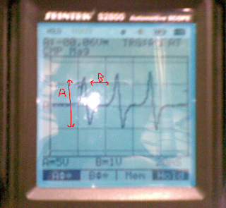
Signal Name; MAP Analoque
Volt/division: 0.5v
Time division: 2 seconds
The output from the sensor with show rise and fall votage dipinding upen the vacuim sens. When the engine is sataitonary or the throttle is wide open zero vacuim will be reduced and voltage reach in this graph nearlly 3 volts will be seen a vacuim is applayed the voltage will reduced. the example waveform clearly demonstrated at idle voltage arorund 1v all the throttle open the vacuim in mainfold drop and higher voltage for these condition Arrow A open throttle Arrow B closed throttle .
Explain in detail an electrical fault that would make this unit operate incorrectly.A bad earth due some grease or dirt, gives a resistance in the earth wire. This would give a lower out put signal voltage this would effect the air/fuel mix, spark advance and injector pulse with.
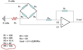
Explain why this condition would cause this unit to malfunction/ Use mathematical equations to back up your explanations.Because there is an extra resistance in the earth wire more voltage will be use up in the MAP sensor circuit. This will cause a lower out put signal voltage. This is a simplified example of a MAP wiring diagram with a resistance in the earth wire.
Without the resistance in the earth wire Vout = 4.5v. The calculations with resistance in the earth wire.
Vd = Vin(R1/R1+R2)
5(10k/10k+28k+10k) = 10000/48000 = 0.2
5x0.2 = 1.04
5-1.04 = 3.9
V1 = 3.9
Vd = 5(10k/10k+4k+10k) = 10000/24000
=0.416
5x0.416 = 2.08
5-2.08 = 2.92
V2 = 2.92
Vout = (V1-V2) Rf/Rin
= (3.9 - 2.92) 1000/5000
0.98x2=1.96
Vout = 1.96
Diffrent betwen good and bad earth 2.5 volts
In this graph is bad earth you can see point voltage is lower than the first graph .
Explain how this condition would affect the operation of the vehicle?
The MAP sensor measures the air intake volume it has a major part in determining how much fuel to inject and also the ignition timing so a low voltage signal would make the engine idle rough or make the engine to stall, or should be engine runing rich or lean.
WS3 General Lab Scope
Make and Modle: Toyota 1ZZ engine
Signal Name: Injector
Volt/division/range: 20 V
Time/division/range: 5 ms
Arrow A shows the supply voltage to the injector in this case 14.4v. Arrow C when the injector is switched on, because the injectors are earth triggered the voltage drops to 0v for approx 2ms this is wile idling. Point B is the voltage spike induced when the earth is switched off approx 60v.
At point D back to EMF.
Fuel injector. supply engine with fuel It remains closed and opens only when fuel needs to be injected, fuel keeps under pressure in the fuel line.
Ws3
Make & Modle: Toyota 1ZZ engine
Signal Name: Oxygen Sensor
Volt/division/range: 0.5V
Time/ division/range: 1s
oxygen sensor. The sensor is part of the emissions control system and feeds data to the engine manegmenment computer. The goal of the sensor is to help the engine run as efficiently as possible and also to produce as few emissions as possible.
Explain the operation of the sensor or device using the graph:
The above graph shows that the engine is running in close loop. It means that engine is warmed up. The point B in graph where it touched the highest voltage shows that the engine is condition is rich and lowest C point shows that it is lean.
WS3 A General Lab Scope
Make & Modle : toyta
Signal Name: RPM (Mag Crank) Analuque
Volt/division/range: 5V
Time/divison/range: 1 ms
When the Magnetic Pulse Generator type is excited by the toothed disc it's in close proximity with, it starts to produce an Analog Voltage Signal. This Analog Signal is created without the help of an external power source! As long as the engine is turning, either because it's cranking or running, the Signal is being produced. When the engine is off, so is the Sensor.
So the analogsignal As it applies to Crank and Cam Position Sensors, it's a signal that oscillates between lows and highs the whole time it's being produced WITHOUT ANY ABRUPT FALLING OR RISING EDGES. When the signal goes low, it never completely turns off. And when it goes high, it must come down again. This process is repeated over and over as long as the toothed disc is exciting it.
Looking at the oscilloscope waveforms at point A high signal and point B falling the signnal.
WS3A General Scope
Make& Modle Toyota 1zz
Signal Name: ECT
Volt/division/range; 1V
Time/division/range: 1S
The ECT sensor cahnge their resistance depending on temperature , as the temperature increasing the resistance of NTC will decreases abuot 240 K ohms at 10 degree to about 200 ohms at 80 deggre. The ECU looks at cslculate signal ECU usually 5 volts supplay is used, that way ECU can calculate the temperature at sensor two resistor in sensor must drop accross the resistance.
I had get this waveform in cold engine that can take time to drop the voltage , on picture the waveform is not change because the engine was cold.
Explaine in detail an electrical faults that would make unit operate incorrectly:
A fault leading to excessive resistance or a lack of resistance in the circuit.] Extreme corrosion at the ECT connector will lead to excessive resistance in the circuit. This condition will raise the ECT signal voltage leading the ECU into calculating that the engine is cooler than it is. A cold engine will make the ECU increase injector pulse-width, therefore, creating excessive CO at the tail pipe. In extreme high resistance conditions, engine flooding can occur, since the ECU reacts as if the engine temperature is at subzero temperatures. If on the other hand, a lack (shorted) of resistance is present at the ECT circuit, the opposite of the previous will hold true. Lower than normal ECT circuit resistance will lower the voltage signal across the sensor tricking the ECU to act if the temperature is higher than what it really is, which in turn makes the ECU reduce injector open time or pulse-width. Such a condition can cause a lean misfire or even a no start on a cold engine, due to the fuel starvation effect caused by the ECU’s reduction of injector pulse width.
Explain why this condition would cause this unit to malfunction / use mathematical equations to back up yor explanation.
First have lock the ECT sensor diagram wich has three resistors one in ECU and two resistors in seriuse inside ECTsensor and 5v refrence from the ECU to sensor.
This one is good working sensor use the calculation :
For example :
Vs=5V
R1= 2000 ohms
R2= 1000 ohms
R3 = 2000 ohms
Calculation: Vout = Vin (R1/R1+R2)
Vout = 5V * 2000ohms/2000ohms+1000ohms= 3.33V
Vout = 3.33V
If in this circuit is connector corrosion there will be resistance in circuit fist look in the diagrm and then we can see the diffrince of output voltge after calculation.
Vout = 5V * 2000 ohms/2000ohsms+1000ohms+1500ohms= 2.22V
Vout = 2.22V
diff : 1.11V
WS3 Grneral Lab Scope
Make & Model: Toyota
Signal Name: RPM (CAM) Analge
Volt/divsion/range: 5V
Time/divsion/range: 20ms
Arrow A peak to peak voltage and Arrow B time in ms.
CMP Sensor is Magnetic Pulse Generator, it will tested with a Multimeter in AC Volts mode. Why? Well, because the Signal that these sensors generate is an Analog Voltage Signal and this Signal can only be measured in AC Volts mode on your Multimeter (or Oscilloscope).
When the Magnetic Pulse Generator type is excited by the toothed disc it's in close proximity with, it starts to produce an Analog Voltage Signal. This Analog Signal is created without the help of an external power source! As long as the engine is turning, either because it's cranking or running, the Signal is being produced. When the engine is off, so is the Sensor we can see on oscilloscope waveform the signal goes high and low , when the signal goes low it;s not complitly turns off and goes high it must go down.
WS3 General Lab Scope
Make & Model: Tyota 4A- FE engine
Volt/division/range: A , 10V & B, 10V
Time/ division/range: 2ms
This is 3 electrical connection with a voltage supplay of battery ether double switched earth path, the rate at switch the earth path is switched is determined by the electronic control moudle (ECU)to maintained by prerequisted speed according to it is programing the double switch earth system will switched the valve in both diricction.


No comments:
Post a Comment